Doki Doki – an emotive wearable for social interaction during covid and beyond

Doki Doki is a responsive, emotive wearable. It was created during the spring / summer of 2020 as a speculative, modular garment that explores forms of nonverbal communication. In particular cues emerging as a reaction to the changes we are facing to our usual rituals of social interaction during the covid pandemic, when faces and micro-expressions may be obscured by the wearing of protective face masks. The garment investigates how data can be visualised both covertly and/or overtly during social and other encounters to communicate information to observers about the wearer, and their environment. But also how data can be conveyed as ‘secret languages’ or signals.

Doki Doki was exhibited as part of the Design Exhibition of the 2021 ACM International Symposium on Wearable Computers (ISWC) and its accompanying paper can be downloaded from here.

Doki Doki montage
Doki Doki emotive wearable, switching between time in binary, heart rate and sensing someone approaching in the darkness

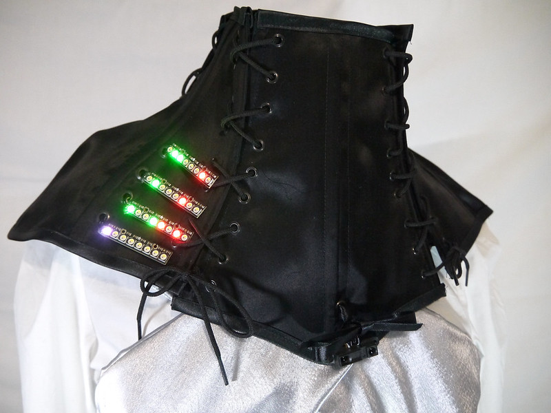
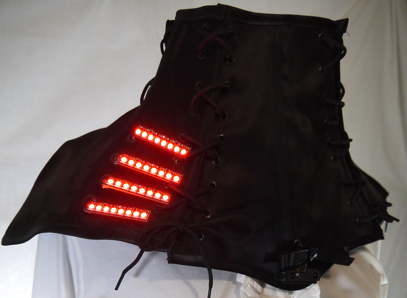
The device uses pattern and colour in the form of four RGB LED NeoPixel bars to visualise data from sensors affixed to a bespoke neck corset. Firstly, the garment functions as a three column binary clock, displaying hours, minutes and seconds. Compared to the 12 hour clock face or numerical 12/24 hour displays, binary is a rarely used method of presenting time in a visual format, and thus is indecipherable by many. This reminds us that there are differing approaches we can use for presenting ubiquitous data.

Doki Doki proximity sensing, emotive wearable
Doki Doki showing time in binary as hours, minutes and seconds on the top three LED arrays and heart rate data on the bottom, which is indicated as changing colours to differentiate from time and proximity data

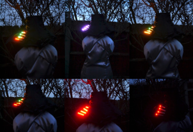
On automatic mode, the LED display periodically switches from visualising the time to amplifying emotive and environmental data. This is in the form of changing heart rate (gleaned from an ear sensor) of the wearer as they respond to social and situational interaction and may be interpreted by the observer as emotive data. When the display is not broadcasting time or heart rate data, it projects spatial data as proximity detection (using an infra red sensor), in relation to the personal space of the wearer. For example, indicating the closeness of someone approaching (in daylight or darkness) and by using LED feedback as a ubiquitous traffic light colour signalling sequence, to warn people if they are getting too near. The wearer can choose, via a button press, between a timed cycling of all data outputs on the display or choosing to display one of the three data outputs singularly. This option may be appropriate when emotive privacy, focus on social distancing or personal boundaries are required.

Doki Doki proximity sensing, emotive wearable
LED arrays in blocks of red light indicating to the observer they are dangerously close for covid social distancing and/or in very close social interaction proximity

In terms of the garment itself, it explores aesthetics, repurposing and sustainability, via a modular plug and play design ethos. The neck collar is made up of four separate boned corset pieces, using traditional corsetry methods and fabrics, which allow for the wearer to tailor the garment to their body for comfort and change its materiality, purpose and aesthetic as required. For example, the corsetry lacing of the garment grants it to be loosened so it may be worn over layers of clothing, or simply by itself. The functionality of the garment can be repurposed, as the sensors and actuators can be swapped and changed, according to the wearer’s bespoke requirements. This is done by the creation of a bespoke plug and play circuit board, and the functionality in the C programming can be easily reprogrammed and updated if the user is familiar with coding.

Using wearables in this way may contribute to the discussion of how and why we might advance the use of covert and overt data on the body to create nonverbal cues and secret languages. Especially, for these devices to be informed by and then react to physiological and environmental situations, and to then aid us in social interaction during the pandemic. But also beyond, as the pandemic requires us to investigate communicating and socialising in different ways it also drives forward the evolution and embodiment of technology. Possibly leading to future acceptance of prominently worn devices on the body where in the past it has been rejected.

Doki Doki proximity sensing, emotive wearable
Doki Doki sensing neck corset front and back views

The next iteration of this project is already underway and includes PCB design and production for streamlining the device’s circuit layout. It also includes an extra mode button. This is necessary as having a single button for all the device’s functionality was not particularly user friendly. The second button will allow differentiation between visualisation modes and data recording. This will be in terms of integrating record and playback functionality, plus for downloading and tracking one’s time-stamped emotive and spatial data. It will allow the analysis of encounters and emotive reactions that can be privately saved for later reflection. Moreover, the use of record and playback allows for the continued ethical discussion around ‘emotive engineering’ where the recording and playback of personal data can be used to influence or change a situation or its outcome.

Twinkle Tartiflette – an Arduino driven interactive word/music artwork

LilyPad Arduino is a great platform for rapid prototyping, for my standalone interactive art projects and wearable artworks. It’s also a fun way to learn about electronics and programming.

Here’s how I created Twinkle Tartiflette, an interactive artwork, using various LilyPad modules connected with conductive thread.
My inspiration came from a Stylophone Beat Box that I recently purchased as a present and had a play with. I pondered how one would go about making an interactive artwork using LilyPad components.

I decided that I wanted to combine words, image and sound into an interactive experience, brought to life by touching the words with a stylus. I began to think about how I’d build this and firstly decided on re-using the frequencies for notes worked out for a favourite ditty, Twinkle Twinkle Little Star, that I’d used in another artwork. I would transfer the first two verses word for word onto felt stars, one star for each verse.

Sewing Twinkle Tartiflette

There are 6 notes in the 2 verses so I needed to map out a schema for the conductive thread to pass from the words to the Lilypad, joining each word to the right note pin on the LilyPad – being careful to select conveniently located pins.
First I cut out 2 star shapes and began sewing the words onto them, not being an experienced embroiderer this wasn’t easy or terribly pretty.

After about a week of evenings I had two stars with conductive thread sewn words in the right order. I was mindful to sew the words carefully so frayed thread did not touch and cause any shorts – fabric glue is good for sticking down frayed thread and keeping close knots apart.

With the word stars completed it was time to deploy the main sewing schema – I’d mapped notes to the words and then words back to pins on the LilyPad.

Twinkle Tartiflette schema

After an intensive couple of weeks of sewing evenings later, I thought I’d sewn all the words to the right notes and pins, also adding buzzer and battery modules. There were some interesting insulation/bridging issues to be solved between the various paths of conductive thread, but I was ready to extract code ideas from my brain to see if it would compile!

The code I have written uses the speaker module to produce simple musical notes from connecting to the words with a stylus. I originally used a chart to match frequencies to the different notes.

Sewing Twinkle Tartiflette with conductive thread

With code loaded to the Lilypad, via an FTDI breakout board, it’s time to test – annoyingly there was a problem! The buzzer was not playing notes correctly, after some thinking and testing with a multimeter, croc clips and a single resistor – a solution was concluded – I’d need to add some resistors.

Unconnected the circuit is connected to high, but when the stylus touches a word it creates a simple circuit through the resistor and pulls it to low, but I needed some resistivity in-between. Looking through a ton of resistors 10k ohm seemed like a good fit, but where and how to add them was another question! A small LilyPad protoboard I had was just the job to solder the resistors to. I have six notes, so the protoboard was just right – I only had 5 x 10k ohm resistors, but found another resistor that was near enough to work (reading up later I found out that 20K pull-up resistors are built into the Atmega chip that can be accessed from software, so I didn’t really need need to add the resistors if I’d known that – hey ho, lesson learnt for next time!).

Soldering resistors to the protoboard

After some soldering, I had some more complex routing of conductive thread to do for the resistors on the protoboard. When testing I discovered I’d fix0red one problem, but had found another to debug! Earlier, I said to be mindful of the pins – I had accidentally connected to pin 13 which is the LED pin and has it’s own resistor which is set too low for this project. This showed up in resistance testing with the multimeter.

The fix for the wrong pin incurred some more unpicking and re-routing of conductive thread. I used an analogue pin as it was nearer and the least hassle to route to, this pin change required to be reflected in the code. Finally I decided the best thing to use for a stylus is a crocodile clip – which worked a treat.

Testing resistance with a multimeter

After all that, yay Twinkle Tartiflette lives! All that remained to do is tidy up the sewing, ensuring there are no trailing bits of conductive thread to cause shorts and gluing down anything looking like it was going to stray or come undone with fabric glue. Lots of lessons learnt, but hurrah!

Twinkle Tartiflette finished

Twinkle Tartiflette & Rain

I’ve made two videos for your delectation below – the first (00:44 secs) is a quick demo of me playing Twinkle Tartiflette.

This second video is an in-depth (05:40 mins) explanation of how I made TT, plus examples of debugging along the way – hope you enjoy!

Here is my code – you can use it via a Creative Commons Attribution-NonCommercial-ShareAlike 3.0 Unported license & I’d love to know if you do!

/*
* Rainycat’s LilyPad stylo style: sound used to power Twinkle Tartiflette
*
* Uses a LilyPad speaker module to produce simple musical notes from touching words to the song
* For a chart of the frequencies of different notes see:
* http://www.phy.mtu.edu/~suits/notefreqs.html
*/

int NotePinC6 = 0; // words connected to play note C6 analogue pin!
int NotePinG6 = 12; // words connected to play note G6
int NotePinA6 = 11; // words connected to play note A6
int NotePinF6 = 10; // words connected to play note F6
int NotePinE6 = 9; // words connected to play note E6
int NotePinD6 = 8; // words connected to play note D6
int speakerPin = 3; // speaker connected to digital pin 3

// A note in one octave is twice the frequency of the same note in the octave
// below. We define here the frequencies of the notes in octave 8. To get
// notes in lower octaves, we just divide by two however many times.

#define NOTE_C8 4186
#define NOTE_CSHARP8 4434
#define NOTE_D8 4698
#define NOTE_DSHARP8 4978
#define NOTE_E8 5274
#define NOTE_F8 5587
#define NOTE_FSHARP8 5919
#define NOTE_G8 6271
#define NOTE_GSHARP8 6644
#define NOTE_A8 7040
#define NOTE_ASHARP8 7458
#define NOTE_B8 7902

// This is an array of note frequencies. Index the array essentially by note
// letter multiplied by two (A = 0, B = 2, C = 4, etc.). Add one to index for
// “sharp” note. Where no sharp note exists, the natural note is just
// duplicated to make this indexing work. The play() function below does all
// of this for you 🙂

int octave_notes[14] = {
NOTE_A8, NOTE_ASHARP8,
NOTE_B8, NOTE_B8,
NOTE_C8, NOTE_CSHARP8,
NOTE_D8, NOTE_DSHARP8,
NOTE_E8, NOTE_E8,
NOTE_F8, NOTE_FSHARP8,
NOTE_G8, NOTE_GSHARP8,
};

// Arduino runs this bit of code first, then repeatedly calls loop() below. So
// all initialisation of variables and setting of initial pin modes (input or
// output) can be done here.

void setup() {
pinMode(13, INPUT); // make sure 13 is high impedance

//pinMode(NotePinC6, INPUT); — analogue pin automatically input
pinMode(NotePinG6, INPUT);
pinMode(NotePinA6, INPUT);
pinMode(NotePinF6, INPUT);
pinMode(NotePinE6, INPUT);
pinMode(NotePinD6, INPUT); // sets the ledPin to be an intput
pinMode(speakerPin, OUTPUT); // sets the speakerPin to be an output

}

// Arduino will run this over and over again once setup() is done.

void loop()
{

// special case hack for this pin:
if (analogRead(NotePinC6) < 256) {
play(speakerPin, "C6", 50);
}
if (digitalRead(NotePinG6) == LOW) {
play(speakerPin, "G6", 50);
}
if (digitalRead(NotePinA6) == LOW) {
play(speakerPin, "A6", 50);
}
if (digitalRead(NotePinF6) == LOW) {
play(speakerPin, "F6", 50);
}
if (digitalRead(NotePinE6) == LOW) {
play(speakerPin, "E6", 50);
}
if (digitalRead(NotePinD6) == LOW) {
play(speakerPin, "D6", 50);
}
}

// ————————————————————————-

// To produce a tone, this function toggles the speaker output pin at the
// desired frequency (in Hz). It calculates how many times to do this to
// produce a note of the desired length (in milliseconds).

void beep(unsigned char speakerPin, int frequency, long duration)
{

int i;
long delayAmount = (long)(1000000/frequency);
long loopTime = (long)((duration*1000)/(delayAmount*2));

//for (i = 0; i = ‘A’ && note[i] = ‘0’ && note[i] >’ operator is a useful shorthand that (for integers
// >= 0) basically translates to “divide by two this many
// times”, so we will use that:

frequency = frequency >> (8 – octave_number);

// Actually play the note!
beep(speakerPin, frequency, duration);
}
}